Optimization of cooling towers
June 23, 2020 0 Comments

Control air and water flows to maximize energy efficiency
Part 1 described the operation of the different cooling tower designs and the nature of the cooling process itself, plus the terms used in connection with it. They include range, which is the ∆T between return and supply water temperatures, and the approach, which is the ∆T between supply water and air wet bulb temperatures. Here, I focus on the control and optimization methods, and on the operating cost reductions that can be obtained by applying these methods.
The load on a cooling tower depends on the flow and temperature of the water returning from the process. The controlled variable is the temperature of the cooling water that is sent back to the process and the manipulated variable is the air flow through the tower, which can be changed either by adjusting the speed of variable-speed fans or by starting and stopping a number of constant-speed fans.
The operating cost of cooling tower operation is the sum of the energy costs of operating the cooling water pumps and the air fans. Optimization minimizes the sum of these costs. Because both the pump and the fan are sized for the maximum process load and worst weather conditions, operating them at full capacity when the load drops is wasteful. Therefore, it is desirable to use variable-speed pumps and fans. If the speeds of the pumps and fans are reduced from 100% to 80%, their operating cost is cut in half, and if their speeds are cut in half, the operating cost drops to 15%.
The initial investment cost of cooling towers is about $40 per GPM of capacity and the energy cost of operation is about 0.01 BHP/GPM, or about $6 per year per GPM if optimized, and about $12 per year per GPM if not. Other costs of operation include water losses: blowdown of 0.5-3.0% of circulated flow rate, evaporation of 1% for each 12.5 °F (7 °C) of cooling range, and drift of 0.02% to 0.1% of circulated flow rate.
Optimized controls
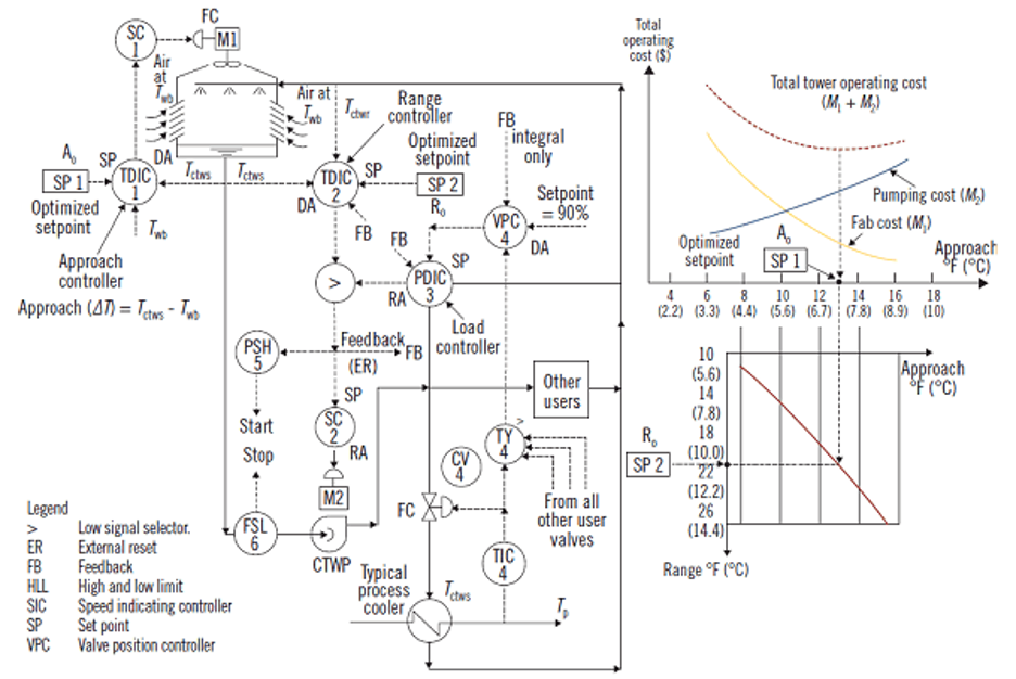
As shown in Figure 1, as the approach, and therefore cooling water temperature (Tctws) rises, the temperature difference across the process cooler (Tp – Tctws) is reduced. This will cause the temperature of the cooled process fluid (Tp) to rise, which in turn will cause its controller (TIC-4) to further open the coolant valve, CV-4. Therefore, as the approach rises, more and more water must be pumped and consequently the pumping costs will rise. At the same time, the fan costs tend to drop as the approach increases.

Control for operating cost
Figure 1: In cooling towers with optimization controls, if the speeds of the pumps and fans are reduced from 100% to 80%, their operating cost will be cut in half, and if their speeds are reduced to 50%, their operating cost drops to 15%.
After adding up the two curves and obtaining the total cost curve, the optimum approach is at the minimum point on that curve. Therefore, the system is optimized when it is operating at that point. The approach controller TDIC-1 in Figure 1 (where TDIC stands for temperature difference indicating controller) serves to maintain its setpoint (SP-1) by throttling the air fan speed to keep the approach at the optimum point.
Figure 1 also shows the optimum range, which corresponds to the optimum approach if all other conditions remain unaltered. Therefore, if the optimum value of approach (SP-1) has been determined, the corresponding optimum range value (SP-2) under the prevailing load conditions can be obtained from this curve. That value is the setpoint (SP-2) of the range controller TDIC-2. This controller keeps the range of the system constant by adjusting the speed of the cooling water pumps.
The optimum pump speed is determined by a valve position controller (VPC-4), which serves to minimize the pressure drops across all cooling water valves in the plant by opening up all of them until the most open one reaches 90% opening. The VPC is integral-only and its integral setting is about 10 times that of the proportional double integral controller (PDIC), so in this cascade loop master VPC-4 is slower than the slave PDIC-3.
It is also recommended to use a selective control configuration, which selects the higher of the outputs of TDIC-2 and PDIC-3 to control the pump speed. This serves to prevent the supply pressure to the user valves from dropping too low.
The data for the cost curves is empirically collected and is continually updated through the actual measurement of fan and pump operating costs. Consequently, for any combination of load and ambient conditions there is a reliable prediction of optimum approach setting. Once the initial prediction is set, that setting can be refined by adjusting it in 0.5 °F increments to check if the total operating cost is lowered by such adjustments.
Optimum supply and return water temperatures
The approach controller optimizes the supply temperature. It is optimized when the water is at the economical minimum temperature. This minimum temperature is a function of both the load and the wet-bulb temperature of the atmospheric air. This temperature can only approach (but not reach) the ambient wet-bulb temperature (hence the term “approach”). The optimum approach will increase if the load on the cooling tower increases or if the ambient wet-bulb temperature decreases.
The approach controller (TDIC-1) controls the cooling water supply temperature from the cooling tower by modifying the air flow as required. This adjustment can occur by changing the fan speed, adjusting the blade pitch or, if the tower fans are two-speed or single-speed units, the output of TDIC-1 will incrementally start and stop the fan units to maintain the optimum approach.
The range controller optimizes the return water temperature. TDIC-2 is the range controller, which is set by the optimized setpoint of SP-2. This is the range value corresponding to the optimum approach. TDIC-2 throttles the water circulation rate to maintain the range at its optimum value.
The load is detected by PDIC-3, and if its output is higher than that of the range controller (TDIC-2), the range controller is selected to set the pump speed. This makes sure that PDIC-3 will not drive the cooling water pressure to unsafe or undesirably high values, because TDIC-2 takes over if the output of PDIC-3 is too high. This load-following optimization loop guarantees that all cooling water users in the plant will always be satisfied while the range is being optimized.
Because the integral mode would otherwise wind up, whenever the output signal of a controller is blocked, it must have external reset from the manipulated variable. In the case of these three controllers (TDIC-2, PDIC-3, VPC-4), because their outputs can be blocked by selection, all three must have external reset feedback (FB in Figure 1).
The control system in Figure 1 guarantees that all users will obtain more cooling (by further opening their supply valves) if needed while the pressure drop in the system is continuously minimized. The VPC-4 setpoint of 90% is adjustable. Lowering it gives a wider safety margin, which might be required if some of the cooling processes served are very critical. Increasing the setpoint maximizes energy conservation at the expense of the safety margin.
In most industrial plants, optimization of the cooling towers is only part of the optimization of the total cooling systems because the temperature of the cooling tower water is not low enough. In such cases, chillers are used to lower the water temperature further, and optimization of the resulting chiller-tower combinations becomes both more complicated and more profitable. These systems I have already described in Optimization of cooling systems.
You can read the original article @
https://www.controlglobal.com/articles/2018/optimization-of-cooling-towers/
Also in Blog

Advanced Cooling Tower Management: Enhancing Efficiency with Lakewood Model 140
February 28, 2024 0 Comments

Optimizing Cooling Tower Performance: Understanding Efficiency, Maintenance, and Water Quality Management
February 28, 2024 0 Comments

Revolutionizing Water Analysis: Everything You Need to Know About the Kemio KEM10DIS
April 19, 2023 0 Comments


